The requirements concerned with the choice of the right microphone for a given application can be summarised as follows:
For speech recording purposes under laboratory conditions, the requirements to be focussed on are the flattest possible frequency response and a specified type of directivity to be as constant as possible over the intended frequency range.
Basically, there are two different physical effects most microphones use to convert acoustic energy into electric energy. Consequently, there are two major groups most microphones can be categorised into, depending on their functional principle.
Since the output impedance of the condenser microphone is high, all condenser microphones contain an impedance converter to render an output impedance of approximately 200Ohm. Therefore condenser type microphones need some kind of power supply not only for the impedance converter but also for the polarisation voltage across the electrodes prescribed by the operation principle. The usual way of supplying condenser microphones besides batteries is the use of a so-called phantom power supply which is connected to the output terminals of the microphone. The standard phantom power supply voltage is 48 V DC. To avoid DC offset on the speech signal, most studio microphones include an integrated optional highpass filter with passband beginning at a frequency slightly above 50Hz.
The construction of unidirectional microphones requires additional engineering effort if a flat frequency response is desired. This is due to the fact that unidirectional microphones respond to the pressure gradient of the sound field, which is frequency dependent. To compensate this dependence, additional tuning, either acoustic or electric, is required in order to yield a flat frequency response.
Moreover, unidirectional microphones show the so-called proximity effect . This effect occurs when spatially confined sound sources are to be picked up. The sound field of small sound sources may be approximated by spherical waves. The pressure gradient in a spherical wave is greater than the pressure gradient in a plane wave by a factor g:
![]()
where r denotes the distance between speaker and microphone, f is the frequency , and c the velocity of sound.
When r decreases, the second term in the equation increases and adds a frequency dependent component to the pressure gradient. Since the unidirectional microphone responds to the pressure gradient of the sound field, this behaviour yields a boosted bass response of the microphone at close talking distances which is termed proximity effect.
The proximity effect is generally unwanted except when recording musical instruments or vocalists, so that the increased bass response has to be compensated for by special microphone design with switchable bass-cut filters. In any case, the proximity puts constraints on the recording setup since it requires the speaker-microphone distance to be fixed when sound coloration is intolerable. The influence of the proximity effect decreases sufficiently when the talking distance is great enough, but this results in a decrease of sound pressure level which in turn has to be compensated for with additional gain at the microphone preamplifier, yielding a higher noise level.
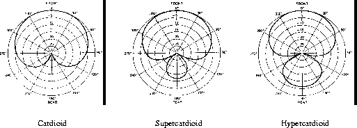
There are several kinds of unidirectional microphone which are classified by the shape of their polar responses (Figure 8.2):

Figure 8.2: Typical polar patterns of various types of unidirectional microphone
Typical applications for these types of microphones with respect to noise suppression are given below:
The bidirectional microphone also exhibits the proximity effect. The effect is approximately 6db stronger as compared to cardioid microphones.
 is basically spheroid but the pickup range is limited by the boundary surface
to a semisphere.
The PZM microphone is recommended for recording situations in which
the talker has to sit at a table.
 ).
).
As already mentioned, a specific recording environment (see also Chapter 4) is either intended or not, depending on the underlying purpose the recording is to be made for. In the latter case, the environment itself as well as any physical feedback to the talker should be virtually non-existent with respect to the actual speech signal, i.e. acoustic feedback like noise , dialogues, or on-line instructions by the recording supervisor has to be conducted via headphones. It is necessary to control environmental conditions by avoiding any undesired room acoustics. Since then the talker has been deprived of his natural acoustic environment, with negative psycho-acoustic effects, some effort must be spent in making up for this (see Section 8.5.2).
For some purposes, e.g. basic phonetic research, when environmental impact on the talking subject is of no or little concern, the efforts can be limited to providing an appropriate ``quiet'' recording ambience (environment). For this, the number of other objects in the recording room apart from the talker himself (e.g. cameras, monitors, amplifiers, etc.), if they cannot be avoided at all, should be as small as possible. The objects should be kept as far away from the microphone as possible and, ideally, should be covered by acoustically absorbent material in order to keep unwanted and unreproducible reflections to a minimum. Furthermore, attention must be paid to the choice of the recording room itself.
For the evaluation of recording spaces for high-quality speech recordings it is necessary to deal with some basic room acoustic properties. Since only few recordings are going to be made in large rooms such as concert halls, it is appropriate to deal with the acoustics of small rooms.
The distinction between large room acoustics and small room acoustics is
necessary since it must be expected that the acoustic properties of a room
vary substantially if its size becomes comparable to the wavelength (![]() )
of sound in the audible frequency range. The latter usually holds true for
relatively small rooms such as those normally used for the production of
speech recordings.
)
of sound in the audible frequency range. The latter usually holds true for
relatively small rooms such as those normally used for the production of
speech recordings.
It is useful to analyse possible problems by looking at the eigenmodes
(roughly, resonance properties) in rooms at different frequencies.
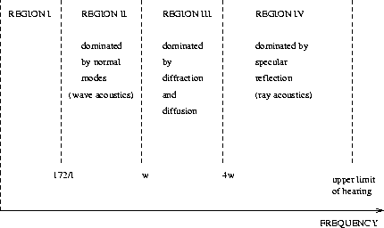
Figure 8.3 shows that the
frequency dependent behaviour of any room may be treated in four frequency
ranges, where variable ![]() denotes the longest dimension of the room and
denotes the longest dimension of the room and
![]() is given as an empirical equation:
is given as an empirical equation:
![]()
with ![]() representing the reverberation time and
representing the reverberation time and ![]() the volume of the room.
the volume of the room.
At very low frequencies in region I the physical dimensions of the room are significantly smaller than the wavelength of sound. Thus, wave propagation is impossible in this frequency range and consequently the room acts as a pressure chamber in which the sound pressure does not depend on the probe position.

Figure 8.3: Closed room pressure zones
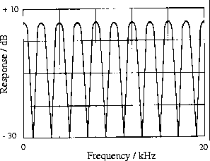
Region II is dominated by the first eigenmodes of the room, i.e. the wavelengths become comparable to the room dimensions. In this frequency region the acoustic properties of the room are best described by wave acoustics. Problems in this zone may arise due to constructive and destructive interference which will introduce comb filter effects when viewed in the frequency domain.
That is, when a sound source radiates sound in the frequency range given by region II, the sound pressure level that can be measured at different locations will extremely depend on the mode distribution in the room. At a fixed microphone position the measurable sound pressure level for a given frequency will depend on whether the standing waves will interfere constructively or destructively at that location.
Thus, in general, the acoustic transfer function between the sound source and the microphone position will not be flat but influenced by comb filter structures as depicted in Figure 8.4.

Figure 8.4: Typical comb filter structure
In large rooms, such as lecture or concert halls, frequency region II will lie well below the relevant frequency range for speech. This is not the case for rather small rooms, such as those often used for speech recordings. In such rooms, region II will often lie well within the speech frequency range, so that these rooms will need a large amount of well-designed acoustic treatment to be usable for the desired purpose.
In particular, the concept of reverberation time, known as a helpful measure from large room acoustics, will fail since the density of eigenmodes is not large enough and each mode has its own separable decay time.
Region III determines a kind of transition behaviour of the room and is dominated by diffraction and diffusion. The rules of wave acoustics have still to be considered, and when approaching the border to region IV, the rules of large room and ray acoustics begin to become valid.
In region IV the wavelength of sound is substantially shorter than the room dimensions so that ray acoustics is a good tool for describing the behaviour of the room.
Recordings made in a laboratory environment are often used to test speech recognition systems, as lab speech recordings seem to reflect best natural speech recognition situations, without requiring too much effort concerning the recording setup.
For standardisation purposes, however, the acoustic environment of a laboratory room is worst suited. Particularly when the recordings are made using a speaker sitting at a desk with the microphone being placed on the desk, the setup will lead to strong destructive interference due to reflections from the table surface.
In the frequency domain, this interference produces comb filter structures as shown in Figure 8.4, which will lead to periodic dips in the spectrum of the recorded speech signal. The frequencies where the dips can be found are dependent on the path difference of the direct and reflected sound and will strongly vary the sound coloration of the recorded speech signal when the speaker moves relative to the microphone or the table.
The kind of environment this equipment provides is, however, not recommended for high quality speech recordings for scientific purposes, since small rooms exhibit strong eigenmodes at relatively high frequencies which may lie well within the speech frequency region. Due to the small dimensions of the booth the acoustic treatment of the inner surface will generally not suffice to provide enough absorption for the resonances to disappear.
As a consequence, speech recordings produced in this environment will exhibit strong linear distortions , i.e. sound coloration.
The major disadvantage of using a recording studio is that the recording conditions and especially the acoustic conditions are not standardised in any way. Moreover, it will generally not be possible to design the acoustic environment of the recording room according to the needs of speech recordings.
The presence of free-field conditions is especially important with respect to the freedom of choice of the proper microphone to be used for recording. In most of the other recording environments discussed, the type of microphone to be used is largely influenced by the properties of the room, e.g. to suppress ambient noise or wall reflections and reverberation. For example, if a studio microphone with selectable directional properties is placed in an anechoic chamber, the sound of the recording does not depend on the selected directivity of the microphone.
Of comparable importance is the fact that the distance of the microphone relative to the speaker is least influential in an anechoic chamber since the microphone is always in the direct sound field of the speaker, and changing the distance only results in changes of the microphone output level as long as the proximity effect is negligible for pressure-gradient microphones.
Problems in the anechoic chamber may arise when a natural talker's response is to be elicited, e.g. in a dialogue situation, and when inexperienced speakers are used. These problems may arise due to the more or less unnatural perceptual effect which the anechoic chamber imposes on the subjects. For this reason, an appropriate form of acoustic feedback to the speaker that gives a natural room impression is highly recommended, especially for lengthy and psycho-acoustically sensitive recordings (see Section 8.5.2).
The subject of this section is the minimum recording chain, i.e. the minimum number of mutually connected components that technically transduce the acoustic speech signal into a sequence of 16 bit numbers stored on digital memory media. As depicted in Figure 8.5, this basically comprises the microphone itself, the preamplifier, the transmission line, and finally, the sampling device.

Figure 8.5: The minimum recording chain
For high-quality speech recordings, the overall noise figure, i.e. the signal-to-noise ratio (SNR) of the setup has to be taken into special consideration. Assuming normal vocal effort and a talking distance of 30cm, the SPL at the microphone capsule should rise to a level of about 75db. If the recording takes place in an anechoic chamber , the ambient noise might level to about 20 dB-SPL such that the SNR at the front end of the recording chain equals to 55db. All subsequent technical devices should be designed and connected to each other in such a way that this input SNR is degraded as little as possible. For a detailed discussion of noise figures and related terms and topics, please refer to Section 8.7.
The microphone should be removed from regions where considerable air flow is to be expected during articulation. A reasonable measure is to situate the microphone about 15 degrees off the direct talking axis.
The first two requirements are met by most preamplifiers built according to
modern technology. The most serious problems occur in making a compromise
between high gain and low noise . In general, noise generated within the
preamplifier should not worsen the signal-to-noise ratio given by the
EIN of the microphone.
The input noise of
high-quality microphone preamplifiers should be less than -125dBu
at 200Ohm input impedance (dBu reference voltage: a0dBu = 0.775![]() or 1mW at 600Ohm),
which roughly corresponds to the thermal noise of a 200Ohm resistor.
or 1mW at 600Ohm),
which roughly corresponds to the thermal noise of a 200Ohm resistor.
Usually, microphone preamplifiers allow the gain to be tuned from 0 to 60db which is sufficient for microphone distances of about maximally 30cm at a reasonably low noise level. Greater microphone distances, e.g. 50-60cm, which may occur when the speech signal is picked up by a PZM microphone placed on a table in front of the talker, require amplifier gain in excess of 60db which may result in audible noise during pauses.
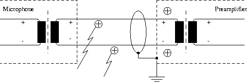
It is standard in the high-quality speech-recording area to use balanced systems, i.e. to feed the speech signal into the recording chain along with its negative (180 degree phase shifted) counterpart (Figure 8.6).

Figure 8.6: Noise cancellation on balanced microphone lines
Since both conductors in a balanced system pick up the same stray signal, noise that has eventually been induced to the system along the feedway can be cancelled out by the summation of the once more inverted signal with its unshifted double.
As stated previously, everything valid for the recording chain in a studio environment in principle holds also true for on-site recordings. A major difference, however, is that in real-life recordings, additional stages may be inserted into the recording chain which exhibit more or less unknown physical properties.
Recommendations on how to use a telephone can not be given. From the technical point of view, however, it has to be mentioned that the speech signal arriving at the receiving telephone has to be by-passed, sampled, and stored at some point prior to the acoustic output, i.e. it should never be captured by a microphone recording of the speech signal emitted from the telephone earpiece.
A coarse distinction between telephone networks can be made in terms of whether they use the analog or the digital signal domain . Whenever the operator has the choice, he should use digital telephone networks (in EU-Europe ISDN-network ). This guarantees best possible signal quality in terms of noise and distortion . At the same time he must be aware of the fact that telephone networks may not be homogeneous in this respect, even within the same network.
Furthermore, the attention of operators must be directed to certain drawbacks of recording speech via the telephone:
A discussion on whether telephone recordings are suitable for a specific purpose or not may be found in Chapters 3 and 4. Details of what kinds of distortion are imposed on a speech signal in a telephone network, and how to get a figure of their magnitude, are given in Section 8.6.
For studio recordings, the data collection stage comprises the A/D-conversion of the analog audio signal and its storage on permanent memory media. We strongly recommend using digital data storage in general, and a hard disk directly connected to the sampling device (computer) in particular.
If all phonetically relevant information in a speech signal is spectrally restricted to a frequency range from 0 to 8.000Hz, the standard sampling frequency of A/D-converters for speech recording purposes, following the sampling theorem, is 16kHz. Appropriate off-the-shelf equipment for speech sampling in real-time should be available for all current computer systems. These would include all filters necessary for proper preprocessing of the analog speech signal according to the sampling theorems. Attention has to be paid to the filters involved: these must be designed to be strictly linear in order to avoid unacceptable phase distortions.
The standard format of speech data is SHORT (16 bits, signed, linear) which corresponds to a representable value range of -32768 up to +32767, i.e. maximum recording dynamics of 96db-SPL. With a properly calibrated microphone preamplifier at the front end, this should suffice for a peak factor in the recording session as well as the projected SNR of about 50db at the microphone output.
Alternatively, a DAT (Digital Audio Tape) may be used to store the speech data. The standard sampling frequency is 48kHz with a 16 bit resolution. This poses less strict requirements in view of the linearity of the filters involved. On the other hand it is rather cumbersome to access recordings made by a DAT for further processing.
When speech has been collected via a digital telephone network it might be necessary to resample the incoming signal according to the required sampling frequency of the recording station. On a digital recording device this is easily achieved by standard algorithms; if a DAT is used to record the digital signal , proper D/A-conversion is necessary. The easiest way to control the domain of the speech data (analog/digital) is to put signal extraction at a position in the receiving telephone that gives access to the data in either analog or digital form. Note in particular that the ISDN signal is encoded as A-law .
The recording procedure comprises a whole range of measures, beginning with the calibration of the microphone and ending with the design of proper interaction between the talking subject and the recording manager. A detailed description of various aspects of concern with regard to the recording procedure is presented in Chapter 4.
From a technical point of view, however, the calibration and the positioning of the microphone is of central interest. It goes without saying that calibration is to be omitted in on-site situations like telephone recordings, for example.
For each of the preceding subsections we give a separate paragraph of recommendations:
The choice of the right microphone strongly depends on the specific task to be performed. In on-site recording situations, often no decision on the microphone can be made. With respect to the best quality obtainable, however, we can give the following recommendations:
In order to achieve speech recordings with minimum environmental (room) distortions the following recommendations should be followed:
In view of the recording chain we may give the following recommendations:
Where the operator has control over components in the recording chain, the recommendations in the preceding section hold true. The field of on-site recordings is quite literally wide open, so that recommendations must be restricted to the very common case of data collection via telephone: