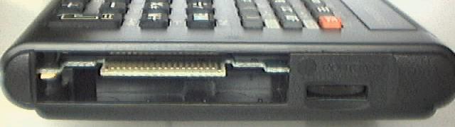
Sharp direc  RS232   Sharp
 pin   tion   name    name    meaning
---------------------------------------------------------------------------
   1    out     ?      BUZ    buzzer signal
   2     -     Vcc     GND     5V
   3     -      SG     Vcc     0V   signal ground
   4    out    CTS     BUSY   (Sharp signals it is busy)
   5    out    DTR     DOUT   if high then Sharp has activated the interface
   6    in     RXD     XIN    Sharp reads data in
   7    out    TXD     XOUT   Sharp sends data out
   8    in     DRS     DIN
   9    in     RTS     ACK    must be high to signal Sharp that it may send data
  10     -      -       -     not connected
  11     -      -       -     not connected
Because usually RS-232 computer levels are between 3 V and 15 V if high and between -15 V and -3 V if low (the range between -3 V and 3 V is dead range for noise absorption), you will need a level converter, which e.g. double respectively half the signal voltages from TTL/CMOS resp. RS232. Also input voltages significantly larger than 6 V may destroy the Sharp pocket computer!
Signal levels:
| RS232 | Inverted CMOS | Sharp IO |
|---|---|---|
| -12 V | 0 V | 5 V |
| +12 V | 5 V | 0 V |
| Port | I/O | usage | used bits | comment |
|---|---|---|---|---|
| 10 | in | key input | 01234567 | returns column vector of a 8x8 resp. 8x2 matrix |
| 11 | out | key strobe | 01234567 | either 0 or choose row of 8x8 matrix via a 1-bit mask for port 10 |
| 12 | out | key strobe | 01______ | either 0 or choose row of 8x2 matrix via a 1-bit mask for port 10 |
| 13 | in | key board | 0_______ | lowest bit indicates status of SHIFT key |
| 14 | in/out | timer | 0_______ | lowest bit indicates timer signal. This is the clock from the LCD driver which has a period of about 0.95 sec |
| 15 | in/out | 11 pin interface | 0______7 | Bit 0 is cleared and Bit 7 indicates pin XIN input enabled/inhibited |
| 16 | in/out | interrupt handling | 0123____ | asks/clears the 4 interrupt reasons: Bit 0 keyboard, Bit 1 ON-Key, Bit 2 timer, Bit 3 CPU-pin INT |
| 17 | out | interrupt handling | 0123____ | enables/disables 4 interrupt sources: Bit 0 keyboard, Bit 1 ON-Key, Bit 2 timer, Bit 3 CPU-pin INT |
| 18 | out/in | 11 pin interface | 01_____7 | Bit 0 pin BUSY/CTS, Bit 1 pin DOUT, Bit 7 XOUT/TXD (complement of data bit) |
| 19 | in/out | bank mapping | 012_____ | adress range C000-FFFF: valid values: 0-7; one of eight banks of internal ROM is selected, current value stored at 7900H |
| in/out | bank mapping | ____456_ | adress range 8000-BFFF: if Bit 6 is set then Bits 4 and 5 address one of four possible 16 kB ROMs on the expansion port | |
| 1A | out | only cleared when BASIC module init | ||
| 1B | out | bank mapping | __2_____ | if Bit 2 is set, an external 32 kB RAM on the expansion port is mapped to 0000-7FFF (cleared when BASIC module init) |
| 1C | out | peripheral reset | 01______ | Bit 0 indicates trigger status and Bit 1 whether low or high signal is supplied |
| 1D | in | battery status | 0_______ | Bit 0 indicates battery status |
| 1E | out | 01______ | ||
| 1F | in | 11 pin interface | 012_____ | Bit 0 pin DIN, Bit 1 pin ACK/RTS and Bit 2 pin XIN/RXD (complement of data bit) |
| in | key board | _______7 | Bit 7 indicates status of ON- resp. break- key | |
| 58 | out | LCD-control | 01234567 | value: column*4+row | 40 , 0 <= column < 24, 0 <= row < 4 |
| 59 | in | LCD-control | _______7 | Bit 7 indicates busy |
| 5A | out | LCD-data | 01234567 | each byte represents 8 successive pixels in a column |
| 5B | in | LCD-data | 01234567 | each byte represents 8 successive pixels in a pixel column |
| V.1 | V.2 | comment | User key |
|---|---|---|---|
| 0 | System/BIOS always at 8000-BFFF | ||
| 1 | Basic Interpreter (mapped default at C000-FFFF) | BASIC | |
| 2 | Peripherial CE-126P (Printer/Cassette) (what still? calculator?) | ||
| 3 | Text Editor / Monitor | TEXT | |
| 4 | Statistics & Fonts | STAT | |
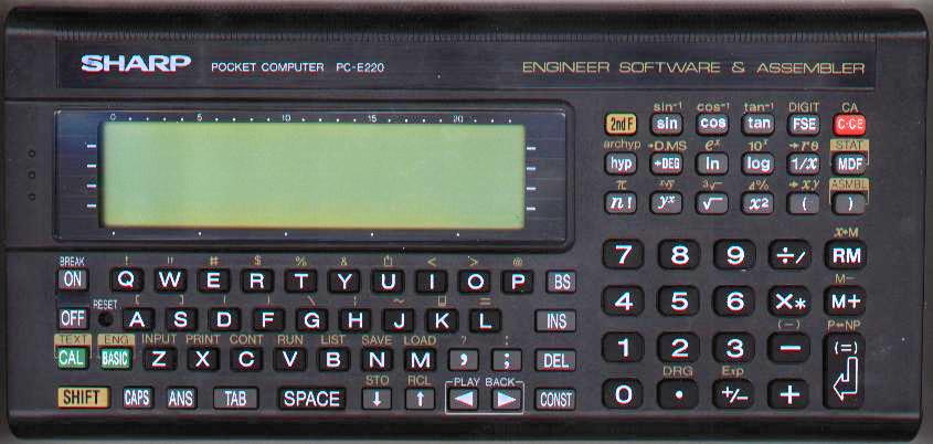
| 5 | 5 | Assembler / Diagnostic modul | ASMBL |
| 6 | 6 | Engineer Software (Integration, Trigonometry, Physical Constant) | ENG |
| 7 | 7 | Engineer Software (Factorization, Metric Conversion, Greek, Complex number) | ENG |
Version .1 and .2 of bank 5 differs only in 3 byte positions.
If both keys SHIFT and , (colon) are pressed during RESET is done
then 5 diagnostic modi are selectable (caution, RAM-Check clears total memory !).
Moreover then the ROM-version, one of V.0, V.1 or V.2, will be displayed.